A short entry today regarding the set up of LTE in Cisco SD-WAN with respect to the ISR1111 routers. For a client, I’m prepping a set of routers and for most branch locations, the ISPs provide an IP over DHCP on their WAN. Similarly, in our case most LTE carriers provide a dynamic IP as well. LTE is, be default, only useable as a fall-back solution. Because of how it functions, it will not work as expected when using a branch routers with a TLOC extension.
The configuration of a TLOC extension is not covered here as there is good material available elsewhere, including on Youtube. Everything in this post relates to VPN 0, the underlay, because we’re looking at building tunnels over the physical infrastructure by using default routes.
- Problem
- Solution 1 - Lower all WAN connections to the same AD as LTE
- Solution 2 - Directly connected networks for the default route
- End result
Problem
Cisco SD-WAN automatically sets a default route for each WAN connection that’s configured. For most WAN connections this happens with an administrative distance of 1 (as in a static route).
Router#sh ip int brief
Interface              IP-Address      OK? Method Status                Protocol
...
GigabitEthernet0/0/1   192.168.178.40  YES DHCP   up                    up
...
Cellular0/2/0          10.22.93.232    YES IPCP   up                    up
Cellular0/2/1          unassigned      YES other  up                    up
...

Router#sh ip route
...

S*    0.0.0.0/0 [1/0] via 192.168.178.1
      10.0.0.0/32 is subnetted, 1 subnets
C        10.22.93.232 is directly connected, Cellular0/2/0
      192.168.178.0/24 is variably subnetted, 2 subnets, 2 masks
C        192.168.178.0/24 is directly connected, GigabitEthernet0/0/1
L        192.168.178.40/32 is directly connected, GigabitEthernet0/0/1
As you can see, the Cellular has an IP address and the subnet is in the routing table, however, there is no load balancing for traffic on the default route over the LTE connection. Whether you would want this or not because of data limits is a different discussion. This can be tweaked separately. So, at this moment, the LTE connection is there, but it won’t be used until the ISP on GigabitEthernet0/0/1 is unreachable and its route is removed from the routing table.
Okay, this can be acceptable to have LTE as a fall-back option only. However, consider the following scenario where you configure a TLOC extension between two routers.
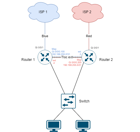
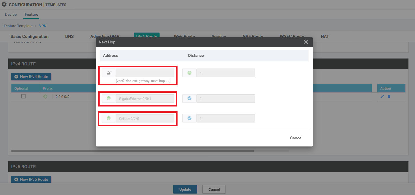
Two branch routers with each having one or more WAN connections directly attached. In order to load-balance, you need to configure a static route in the VPN 0 template that has a similar administrative distance, similar to shown below.
The show ip interface brief and show ip route will have the following output:
Router#sh ip int brief
Interface              IP-Address      OK? Method Status                Protocol
GigabitEthernet0/0/0   unassigned      YES other  up                    up
Gi0/0/0.100            192.168.255.2   YES other  up                    up
Gi0/0/0.200            192.168.255.4   YES other  up                    up
GigabitEthernet0/0/1   192.168.178.40  YES DHCP   up                    up
...
Cellular0/2/0          10.22.93.232    YES IPCP   up                    up
Cellular0/2/1          unassigned      YES other  up                    up
...

Router#sh ip route
...
Gateway of last resort is 192.168.255.5 to network 0.0.0.0

S*    0.0.0.0/0 [1/0] via 192.168.255.5
                [1/0] via 192.168.178.1
      10.0.0.0/32 is subnetted, 1 subnets
C        10.22.93.232 is directly connected, Cellular0/2/0
      192.168.178.0/24 is variably subnetted, 2 subnets, 2 masks
C        192.168.178.0/24 is directly connected, GigabitEthernet0/0/1
L        192.168.178.40/32 is directly connected, GigabitEthernet0/0/1
      192.168.255.0/24 is variably subnetted, 4 subnets, 2 masks
C        192.168.255.2/31 is directly connected, GigabitEthernet0/0/0.100
L        192.168.255.2/32 is directly connected, GigabitEthernet0/0/0.100
C        192.168.255.4/31 is directly connected, GigabitEthernet0/0/0.200
L        192.168.255.4/32 is directly connected, GigabitEthernet0/0/0.200
So, let’s say both ISPs fail. Not a totally unlikely scenario in some countries with local power failure, power spikes or in places where there is really only one ISP. Maybe there is even a cable cut and both ISP entered the building via the same street corner, who knows?
Regardless, what happens is that the two routers will keep seeing each other via the configured link. This means that the “default” route to the neighbor will stay up whether it has a working WAN connection or not. There is no way to fix this via tracking or anything (at the moment of writing).
The result is that there is no fall-back to the LTE connection without manual intervention. You either need to power off the secondary router or at the very least disconnect the cable connecting both.
Ideally, you would now have that LTE connection be up and running with a default route in your routing table. There are two solutions for this issue and I prefer the second one. However, that solution was not available in older software versions. In this case, I’m running 16.12.4 on the routers and 19.2.3 on the vManage.
Solution 1 - Lower all WAN connections to the same AD as LTE
The first possible solution is a workaround for the fact that you can’t increase the administrative distance on the LTE connection. So, we decrease the administrative distance on the other connections.
Directly connected WAN connections
You will need the following line of code in case of using a CLI configuration method:
sdwan
  interface GigabitEthernet0/0/1
    ip dhcp client default-router distance 254
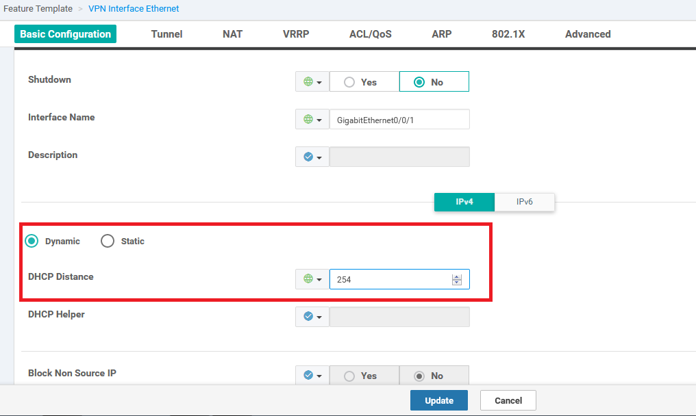
For those configuring via the device template, this setting can be found in the WAN Edge Interface feature template for VPN 0. Under DHCP Distance the value can be set to match the LTE AD.
TLOC extensions
For the TLOC extension, you will need the following line of code:
  vpn 0
   ip route 0.0.0.0/0 192.168.255.5 254
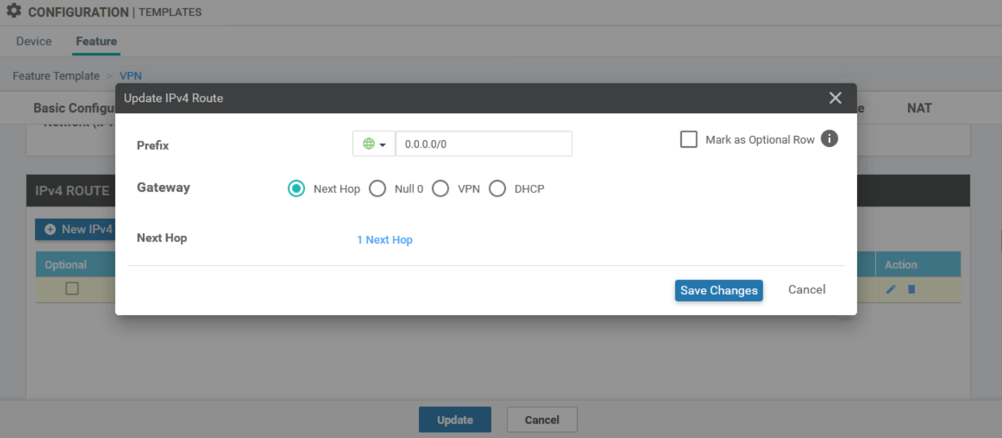
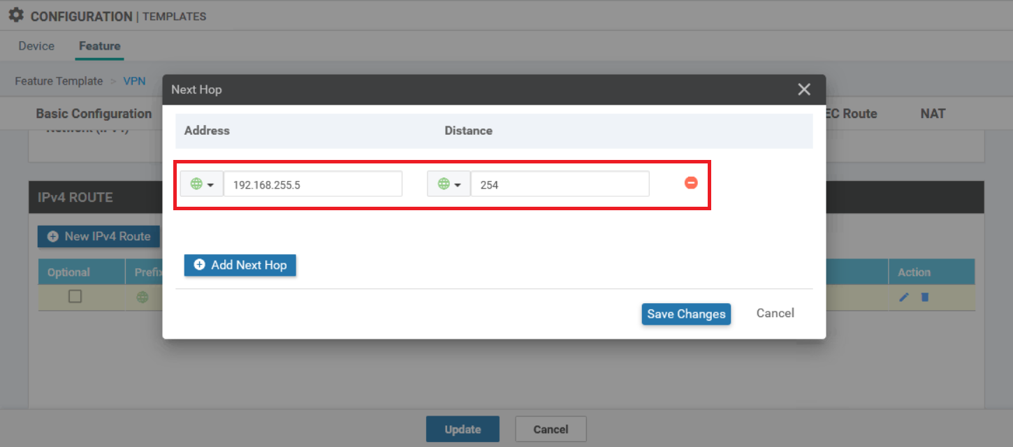
When using the feature templates, you need to open the WAN Edge VPN template that you configured for VPN 0. Set the AD on the next hop to 254.
Solution 2 - Directly connected networks for the default route
This was a solution I tested out together with Cisco TAC, because I didn’t really like the idea of having an AD of 254. I’m always thinking of possible corner cases that might come back to haunt you. The thinking here is that when you provide the next hop interface, then all routes have the best administrative distance they can get.
  vpn 0
   ip route 0.0.0.0 0.0.0.0 Cellular0/2/0 1
   ip route 0.0.0.0 0.0.0.0 GigabitEthernet0/0/0.200 1
   ip route 0.0.0.0 0.0.0.0 GigabitEthernet0/0/1 1
The AD on this one won’t really matter as the router will recognize the route as being directly connected anyway.
When using the feature templates, you need to open the WAN Edge VPN template that you configured for VPN 0.
End result
Below is the end result after applying the first solution. However, with the second solution, the routing table is near identical and it has the same result when disconnecting both wired ISP connections.
Router#sh ip int brief
Interface              IP-Address      OK? Method Status                Protocol
GigabitEthernet0/0/0   unassigned      YES other  up                    up
Gi0/0/0.100            192.168.255.2   YES other  up                    up
Gi0/0/0.200            192.168.255.4   YES other  up                    up
GigabitEthernet0/0/1   192.168.178.40  YES DHCP   up                    up
...
Cellular0/2/0          10.22.93.232    YES IPCP   up                    up
Cellular0/2/1          unassigned      YES other  up                    up
...

Router#sh ip route
...

Gateway of last resort is 192.168.255.5 to network 0.0.0.0

S*    0.0.0.0/0 [254/0] via 192.168.255.5
                [254/0] via 192.168.178.1
                [254/0], Cellular0/2/0
...
When testing by disconnecting both wired ISP connections, this is the result:
Router#sh ip route
...

Gateway of last resort is 192.168.255.5 to network 0.0.0.0

S*    0.0.0.0/0 [254/0] via 192.168.255.5
                [254/0], Cellular0/2/0
      10.0.0.0/32 is subnetted, 1 subnets
...
Router#ping 8.8.8.8 source Cellular 0/2/0
Type escape sequence to abort.
Sending 5, 100-byte ICMP Echos to 8.8.8.8, timeout is 2 seconds:
Packet sent with a source address of 10.22.93.232
!!!!!
Success rate is 100 percent (5/5), round-trip min/avg/max = 28/30/32 ms
Router#
Router#ping vrf 1 x.x.x.x
Type escape sequence to abort.
Sending 5, 100-byte ICMP Echos to x.x.x.x, timeout is 2 seconds:
!!!!!
Success rate is 100 percent (5/5), round-trip min/avg/max = 48/63/80 ms
Router#sh sdwan control connections
                                                                                       PEER                                          PEER                                          CONTROLLER
PEER    PEER PEER            SITE       DOMAIN PEER                                    PRIV  PEER                                    PUB                                           GROUP
TYPE    PROT SYSTEM IP       ID         ID     PRIVATE IP                              PORT  PUBLIC IP                               PORT  LOCAL COLOR     PROXY STATE UPTIME      ID
----------------------------------------------------------------------------------------------------------------------------------------------------------------------------------------
vsmart  dtls 1.1.1.4         4294951074 1      10.0.2.40                               12446 a.a.a.a                            12446 lte             No    up     0:00:09:41  0
vsmart  dtls 1.1.1.5         4294951075 1      10.0.5.170                              12446 b.b.b.b                            12446 lte             No    up     0:00:09:53  0
vmanage dtls 1.1.1.6         4294951076 0      10.0.5.193                              12846 c.c.c.c                             12846 lte             No    up     0:00:09:43  0