This post describes the setup of VPCs on a data center interconnect and HSRP as the first hop redundancy protocol for the VLAN interfaces (SVIs). This configuration has been performed on a Nexus 93180YC-EX with software version 7.0(3)I7(8). The switches have the system default switchport command set, so all ports are switchports by default, but this does not matter for the setup.
Background
This configuration is for a setup where the current network “core” is a Catalyst 6500 in VSS mode with a chassis in each data center. This has some benefits in terms of a single management plane for example. The problem with this device was that the customer didn’t have enough line cards to provide redundancy to all connected devices. Two extra line cards per chassis were almost the same cost as 4 Nexus 93180YC-EX switches with some extra gbic SFPs. The reason to go for this particular model is that it allows to use both fiber and gbic SFPs in the same slot. The size of the customer did not allow for more switches, thus going with this flexible switch model combined with gbic SFPs was the reasonable choice.
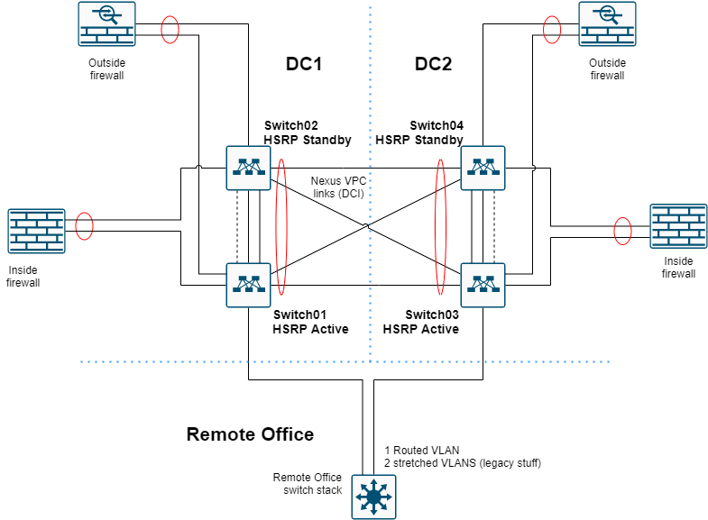
Each data center has 2 Nexus switches configured in a VPC domain. They connect to the other data center location via a LACP-VPC link. To provide high availability, each Nexus has all the SVIs of all the other Nexus switches, because the VLANs span both data centers. The SVIs in turn are configured with HSRP as first hop redundancy protocol. The HSRP is isolated via an ACL so that each data center has the gateway local and traffic does not needlessly need to traverse the DCI.
The migration strategy will differ heavily per scenario and requirements. In this setup, I went with a L2 connection to the VSS to easily move SVIs in each data center and rollback when necessary to the VSS. After everything is connected to the Nexus switches and tested, the VSS was disconnected from the Nexus switches. The VSS remained operational by itself (without anything attached) for another week, just in case. Afterwards, the VSS was decommissioned and the fibers previously in use by the VSS were added to the Nexus LACP links as extra data links for the DCI (data center interconnect).
VPC configuration
To perform a VPC configuration, you need to activate the vpc feature with feature vpc. Below is a code snippet of the first Nexus switch.
vrf context keepalive

interface Ethernet1/48
  no switchport
  vrf member keepalive
  ip address 10.40.98.1/30
  no shutdown

vpc domain 1
  peer-switch
  role priority 1
  system-priority 8192
  peer-keepalive destination 10.40.98.2 source 10.40.98.1 vrf keepalive
  peer-gateway
  ip arp synchronize
The IP addresses are configured in a separate VRF that has no routing entries. The IP addresses are not used elsewhere in the network.
The other switch in the VPC pair needs to have the destination and source addresses reversed. It’s also important to remember that the secondary location needs to be configured with another VPC domain ID. Nexus VPC domains allow only two devices per domain. If not, you might experience problems with traffic forwarding and establishing LACP tunnels (non-LACP port-channels will establish, but you might experience problems with traffic forwarding).
I configured the peer-switch and peer-gateway because I want both Nexus switches to forward L2 and L3 traffic by themselves.
Configuring the DCI
To configure the DCI, in this example I use port Ethernet 1/46. After configuring the basics for the port, the rest can be applied to the port-channel. Below is a code snippet of the first Nexus switch.
conf t
interface Ethernet1/46
  description To_DC2
  switchport mode trunk
  channel-group 999
  no shutdown
interface port-channel999
  description To_DC2
  switchport mode trunk
  spanning-tree port type
  vpc 999
Later on, I added the additional links that were used by the VSS for extra bandwidth and redundancy. Those links have a similar config to Ethernet1/46.
HSRP configuration
So why use HSRP? First of all, for each VLAN that is routed by the Nexus switches, you want to have a single gateway IP - a VIP. Each Nexus switch has its own IP addresses assigned to the SVI, so using a first hop redundancy protocol makes it a lot easier and transparent to the connected hosts. Second, HSRP is cisco proprietary and the design involves blocking HSRP traffic between the two data centers so each data center has its own gateway per VLAN. This drastically reduces the traffic load on the DCI and potential latency for a routed packet. Because the FHRP is to be blocked between the two data centers, it’s preferable to use HSRP for this. That way, VRRP is still available for other instances that need a FHRP, such as the firewall clusters. The firewalls wouldn’t be able to speak HSRP in the first place, because in this case, they’re not Cisco branded. Therefore, choosing HSRP for the Nexus platform makes the most sense.
To perform a HSRP configuration, you need to activate the vpc feature with feature hsrp. Below is a code snippet of the first Nexus switch.
interface Vlan100
  description SOME_VLAN
  no shutdown
  no ip redirects
  ip address 10.10.0.250/24
  no ipv6 redirects
  no ip ospf passive-interface
  no ip arp gratuitous hsrp duplicate
  hsrp version 2
  hsrp 100
    preempt delay reload 60
    priority 120
    ip 10.10.0.254
HSRP version 2 is here configured mainly for purposes of matching the VLAN ID to the HSRP group ID. It’s a Cisco recommendation to use a different group per VLAN or subnet.
HSRP ACL
In this design the idea is to get two HSRP primaries, one for each data center so that traffic can be routed on-site instead of traversing the DCI. To accomplish this, HSRP traffic has to be limited to the each location. To achieve this, an HSRP access list has to be set up, applied to the port-channel as well as prevent gratuitous arp on each VLAN SVI that is present in both locations.
NOTE: By default, the switches I was using did not allow for port access-groups due to insufficient TCAM memory allocation. Please refer to the troubleshooting section if you notice similar behavior - Errors related to TCAM entries.
ip access-list DENY_HSRP_IP
  10 deny udp any 224.0.0.2/32 eq 1985
  20 deny udp any 224.0.0.102/32 eq 1985
  30 permit ip any any
interface port-channel999
  ip port access-group DENY_HSRP_IP in
interface Vlan100
  no ip arp gratuitous hsrp duplicate
Spanning Tree
You might also want to consider the spanning-tree topology. Whatever you do, make sure the two VPC peers always have a similar spanning-tree priority. They are seen as one and the same switch to everything that is attached, including the Nexus switches in the other data center.
Because two VLANs are stretched to a tertiary location, I wanted to control spanning-tree a bit more precisely. I used the long method because of the high speed links and defined the DC1 switches are the primary for all VLANs. However, setting that priority is not necessary when you don’t have to worry about another location or, in my case, having the old VSS switches still attached for a short while.
NOTE: VLAN 3967 is as high as NXOS let’s you configure.
spanning-tree pathcost method long
spanning-tree vlan 1-3967 priority 4096
Furthermore, it’s advisable to use a BPDU filter on the DCI and activate storm-control to limit broadcast traffic.
interface port-channel999
  spanning-tree bpdufilter enable
  storm-control broadcast level 1.00
Troubleshooting
When configuring this, I ran into a few issues myself. I’ve provided the solutions to these issues below. The guides I used were written for Nexus 7k and were therefore not 1-on-1 applicable to the Nexus 9K platform.
Errors related to TCAM entries
The logs can show a warning relating to the TCAM (ing-ifacl) memory state for ingress PACL.
2020 Jun 10 11:38:14 Switch01 %ACLQOS-SLOT1-2-ACLQOS_FAILED: ACLQOS failure: TCAM region is not configured for feature PACL class IPv4 direction ingress. Please configure TCAM region Ingress PACL [ing-ifacl] and retry the command.
2020 Jun 10 11:38:14 Switch01 %ETHPORT-5-IF_SEQ_ERROR: Error ("TCAM region is not configured. Please configure TCAM region and retry the command") communicating with MTS_SAP_ACLMGR for opcode MTS_OPC_ETHPM_BUNDLE_MEMBER_BRINGUP (RID_PORT: Ethernet1/46)
2020 Jun 10 11:38:14 Switch01 %ETHPORT-5-IF_DOWN_PORT_CHANNEL_MEMBERS_DOWN: Interface port-channel999 is down (No operational members)
2020 Jun 10 11:38:14 Switch01 last message repeated 1 time
2020 Jun 10 11:38:14 Switch01 %ETHPORT-5-IF_DOWN_ERROR_DISABLED: Interface Ethernet1/46 is down (Error disabled. Reason:TCAM region is not configured. Please configure TCAM region and retry the command)
To view the current setup and allocate memory, you can use show system internal access-list globals. Here you can see how much is allocated and in use. You might need to free up some memory elsewhere in order to allocate it to the ingress interface ACL (PACL).
Switch01(config)# show system internal access-list globals

slot  1
=======


  Atomic Update : ENABLED
  Default ACL   : DENY
  Bank Chaining : DISABLED
  Fabric path DNL : DISABLED
  NS Buffer Profile: Burst optimized
  Min Buffer Profile: all
  EOQ Class Stats: qos-group-0
  NS MCQ3 Alias: qos-group-3
  Ing PG Share: ENABLED
  IPG in Shape: DISABLED
  Classify ns-only : DISABLED
  Ing PG Min: NOT-DISABLED
  Ing PG Headroom reservation: 100
  OQ Drops Type: both
  OQ Stats Type:   [c0]: q 0 both
  [c1]: q 1 both
  [c2]: q 2 both
  [c3]: q 3 both
  [c4]: q 4 both
  [c5]: q 5 both
  [c6]: q 6 both
  [c7]: q 7 both
  [c8]: q 8 both
  [c9]: q 9 both
  peak count type: port
  counter 0 classes: 255
  counter 1 classes: 0
  OOBST Max records: 1000
  DPP Aging Period: 5000
  DPP Max Number of Packets: 120
  AFD ETRAP Aging Period: 50
  AFD ETRAP Byte Count: 1048555
  AFD ETRAP Bandwidth Threshold: 500
  ACL Inner Header Match : DISABLED
  ACL Inner Header Match : DISABLED

  LOU Threshold Value : 5

--------------------------------------------------------------------------------------
                 INSTANCE 0 TCAM Region Information:
--------------------------------------------------------------------------------------
Ingress:
--------
                    Region          TID     Base     Size     Width
--------------------------------------------------------------------------------------
                         NAT         13        0        0         1
                Ingress PACL          1        0        0         1
                Ingress VACL          2        0        0         1
                Ingress RACL          3        0     1792         1
               Ingress RBACL          4        0        0         1
              Ingress L2 QOS          5     1792      256         1
         Ingress L3/VLAN QOS          6     2048      512         1
                 Ingress SUP          7     2560      512         1
         Ingress L2 SPAN ACL          8     3072      256         1
    Ingress L3/VLAN SPAN ACL          9     3328      256         1
               Ingress FSTAT         10        0        0         1
                        SPAN         12     3584      512         1
            Ingress REDIRECT         14        0        0         1
                 Ingress NBM         30        0        0         1
-------------------------------------------------------------------------------------
Total configured size: 4096
Remaining free size: 0
Note: Ingress SUP region includes Redirect region

Egress:
--------
                    Region          TID     Base     Size     Width
--------------------------------------------------------------------------------------
                 Egress VACL         15        0        0         1
                 Egress RACL         16        0     1792         1
                  Egress SUP         18     1792      256         1
               Egress L2 QOS         19        0        0         1
          Egress L3/VLAN QOS         20        0        0         1
-------------------------------------------------------------------------------------
Total configured size: 2048
Remaining free size: 0


--------------------------------------------------------------------------------------
                 INSTANCE 1 TCAM Region Information:
--------------------------------------------------------------------------------------
Ingress:
--------
                    Region          TID     Base     Size     Width
--------------------------------------------------------------------------------------
                         NAT         13        0        0         1
                Ingress PACL          1        0        0         1
                Ingress VACL          2        0        0         1
                Ingress RACL          3        0     1792         1
               Ingress RBACL          4        0        0         1
              Ingress L2 QOS          5     1792      256         1
         Ingress L3/VLAN QOS          6     2048      512         1
                 Ingress SUP          7     2560      512         1
         Ingress L2 SPAN ACL          8     3072      256         1
    Ingress L3/VLAN SPAN ACL          9     3328      256         1
               Ingress FSTAT         10        0        0         1
                        SPAN         12     3584      512         1
            Ingress REDIRECT         14        0        0         1
                 Ingress NBM         30        0        0         1
-------------------------------------------------------------------------------------
Total configured size: 4096
Remaining free size: 0
Note: Ingress SUP region includes Redirect region

Egress:
--------
                    Region          TID     Base     Size     Width
--------------------------------------------------------------------------------------
                 Egress VACL         15        0        0         1
                 Egress RACL         16        0     1792         1
                  Egress SUP         18     1792      256         1
               Egress L2 QOS         19        0        0         1
          Egress L3/VLAN QOS         20        0        0         1
-------------------------------------------------------------------------------------
Total configured size: 2048
Remaining free size: 0
As you can see, I had 0 remaining free space, so I removed some memory from the RACL allocation and assigned it to the ingress PACL. This works in increments of 256.
conf t
 hardware access-list tcam region ing-racl 1536
 hardware access-list tcam region ing-ifacl 256
end
Reload the device and wait for it to come back. Don’t forget to save your config beforehand though!
After reboot, you can find the readdressed memory:
Switch01# sh hardware access-list tcam region
                                    NAT ACL[nat] size =    0
                        Ingress PACL [ing-ifacl] size =  256
                                     VACL [vacl] size =    0
                         Ingress RACL [ing-racl] size = 1536
                       Ingress RBACL [ing-rbacl] size =    0
                     Ingress L2 QOS [ing-l2-qos] size =  256
           Ingress L3/VLAN QOS [ing-l3-vlan-qos] size =  512
                           Ingress SUP [ing-sup] size =  512
     Ingress L2 SPAN filter [ing-l2-span-filter] size =  256
     Ingress L3 SPAN filter [ing-l3-span-filter] size =  256
                       Ingress FSTAT [ing-fstat] size =    0
                                     span [span] size =  512
                          Egress RACL [egr-racl] size = 1792
                            Egress SUP [egr-sup] size =  256
                 Ingress Redirect [ing-redirect] size =    0
                      Egress L2 QOS [egr-l2-qos] size =    0
            Egress L3/VLAN QOS [egr-l3-vlan-qos] size =    0
                           Ingress NBM [ing-nbm] size =    0